By: Paul McMinn, Sr. Mechanical Engineer, Fauske & Associates, LLC
Introduction
Recent events in the nuclear industry have demonstrated the importance of understanding and mitigating the effects of flammable gas (hydrogen and carbon monoxide) generation under accident conditions in a nuclear reactor. Mitigation of the risks due to flammable gas combustion is vital to ensuring the safety of the public, plant personnel, and the reactor.
Nuclear regulatory bodies around the world require mitigation of flammable gas risks to containment, but the equipment used to mitigate the risks differs from plant to plant and country to country. The use of Passive Autocatalytic Recombiners (PARs) is becoming more and more common around the world as a tool to mitigate the flammable gas risks to containment. PARs are completely passive safety systems that operate by combining hydrogen (H2) or carbon monoxide (CO) with oxygen on a catalytic surface to form water or carbon dioxide. This process removes the flammable gases from containment in a safe and controlled manner. A plant-specific analysis is required to determine the proper number of PARs to be installed into containment and the best locations at which to install them.
Risks
In the unlikely event of a severe accident in a nuclear reactor, flammable gas can be generated in two distinct phases. Hydrogen can be generated by oxidation of the zirconium fuel cladding by steam when the fuel first uncovers and begins to heat up. This is referred to as the in-vessel flammable gas generation phase because it occurs while the core material is within the reactor vessel. The other flammable gas generation phase is the ex-vessel phase. This phase occurs after the core material has melted through the reactor vessel and has fallen onto the concrete floor of the containment. Both hydrogen and carbon monoxide are generated by the interaction of the metallic material in the core melt with the oxidizing gases produced by thermally decomposing concrete. The in-vessel phase generates flammable gas much more rapidly, but the ex-vessel phase progresses over a significantly longer duration.
Flammable gases migrate through containment and can be mixed or concentrated by the operation of various safety systems. If flammable gas concentrations reach sufficient levels, they can be ignited by even a weak ignition source. Ignition of high concentrations of flammable gases can challenge containment by either static or dynamic pressure loading in excess of the structure’s capacity. Analysis of the static pressure load that can be generated by a flammable mixture is done using an assumption of Adiabatic Isochoric Complete Combustion (AICC). However, the effective pressure loads generated due to Flame Acceleration (FA) or Deflagration to Detonation Transition (DDT) can exceed the pressure calculated using AICC assumptions.
Flame acceleration is a phenomenon where a slow-moving flame front transitions to a fast-moving flame front. This occurs due to a complex interaction of chemistry and turbulence that causes a self-reinforcing acceleration of the propagating flame. Fast moving deflagrations produce effective pressure loads higher than slow moving deflagrations and can even transition into detonations under the proper conditions. Flammable gas detonations can be extremely damaging to both the containment structure and the equipment in containment that is required to mitigate the radiological releases from a severe accident.
Analysis
The Modular Accident Analysis Program version 5.04 (MAAP5.04)* is software that analyzes the full scope of a severe accident in a nuclear reactor [EPRI, 2016]. With the proper modeling methodology, this software can be used to calculate the flammable gas generation, migration, and combustion risk within the containment. MAAP5.04 was recently used by FAI to calculate the number of PARs that would need to be installed into a Large Dry PWR containment in order to prevent significant flammable gas combustion events.
* The Modular Accident Analysis Program (MAAP) severe accident code is software owned and licensed by EPRI (Electric Power Research Institute)
The first step to analyzing the number of PARs that are required to prevent flammable gas risks was the creation of a detailed model representing the nuclear reactor. This model was created to represent the plant-specific configuration of the reactor core, primary system, steam generators, and containment building. Specific attention was paid to the representation of the containment building because the containment design and modeling has a strong influence on the quantity and distribution of flammable gases.
The most critical time frame of the analysis was a period lasting for about 10 hours after the time of reactor vessel failure. 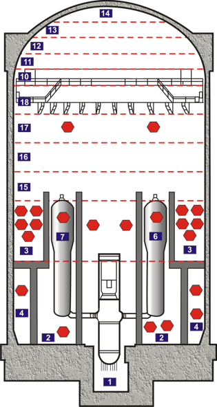 During this time period, molten core material spills onto the floor of the reactor cavity and begins to melt the concrete. This process produces a steady supply of flammable hydrogen and carbon monoxide gases in the confined area near the reactor vessel. These hot, flammable gases flow out of the reactor cavity as buoyant plumes, carrying high concentrations of flammable gas into the uppermost regions of the containment structure. The accumulation of flammable gas within containment was analyzed to determine the potential for local regions to achieve conditions that would support destructive combustion events. Three key metrics were calculated throughout the containment structure to determine the destructive potential of flammable gas combustion: (1) the AICC pressure, (2) the FA index, and (3) the DDT index.
Results
Several iterations of selected accident sequences were run to investigate various numbers of PARs positioned within various locations in containment. The results are shown below for the most challenging case that still resulted in successful mitigation of flammable gas risks to containment. The most challenging type of accident scenario was found to be a scenario with containment cooling provided only by fan coolers. When containment sprays are available, the containment remains cool and well-mixed. When no systems are available to remove decay heat from the containment, the containment atmosphere is inerted by high concentrations of steam, preventing the hydrogen and carbon monoxide from being flammable. The key criterion for success in the case with only containment fan coolers available is that the number of PARs is sufficient to keep the flammable gas concentration below the limits for downward flame propagation. When concentrations are below this limit, ignitions result only in incomplete burns that cannot support flame acceleration or cause pressures high enough to challenge containment.
Sample results are shown below for one of the sequences with containment fan coolers providing decay heat removal. Figure 2 through Figure 6 show the distributions of gas species throughout containment. It can be seen from the figures that MCCI begins near 20,000 seconds into the sequence. The progression of MCCI results in a plume of hot gas rising from the annulus around the reactor vessel. The hot plume rises to the top of containment, entraining cooler gas along the way. This process leads to a relatively well-mixed containment. The behavior of the plume emanating from the reactor cavity is visualized in Figure 8.
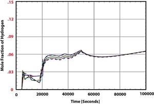
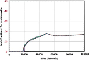
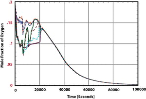
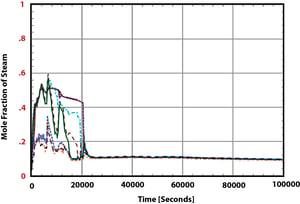
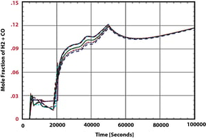
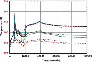
Figure 7 shows the distribution of temperature throughout the gas space within containment. The temperature is fairly high (above 400 K) throughout the upper portions of containment. The high temperature and high total flammable gas concentration are sufficient to produce a calculated flame acceleration index above 1.0. A plot of flame acceleration index is shown in Figure 8 for various regions throughout containment. However, even though the flame acceleration index is calculated to be above 1, the flammable gas concentrations are insufficient to support downward flame propagation. Despite a total (combined) flammable gas concentration above 10%, there is insufficient hydrogen in the mixture and it is not downwardly flammable. Thus, this sequence is a success. The PARs operate to keep the flammable gas concentration below the threshold that would support destructive combustion events.

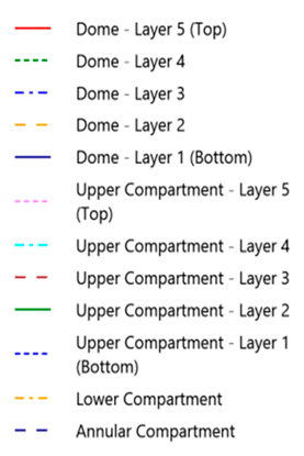
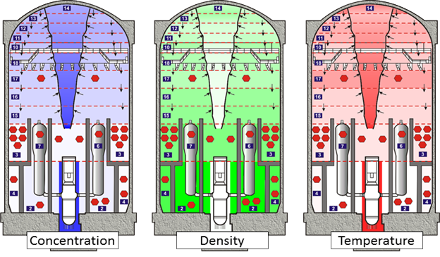
Figure 9 Visualization of Containment Conditions Approximately 6 hours After Vessel Failure. The image on the left depicts the flammable gas concentration, the image in the middle depicts the density, and the image on the right depicts the temperature.
Summary
Passive autocatalytic recombiners (PARs) are being increasingly utilized around the world to reduce the risks that stem from flammable gas generation during the unlikely event of a severe accident in a nuclear reactor. The design of these hydrogen mitigation systems can be optimized using the MAAP code by applying detailed modeling and knowledge of combustion phenomena. This allows for a comprehensive analysis of many potential accident types to determine the system response under the possible conditions. The risks of containment failure due to hydrogen and carbon monoxide combustion can be mitigated by a properly designed hydrogen control system that includes PARs.
References
EPRI, “User Manual for MAAP5 Code Revision MAAP 5.04”, FAI/16-0951, EPRI Product ID: 3002007340, Palo Alto, September 2016.

