By: Jens Conzen, Director Plant Services, Fauske & Associates
Typical power and process plant systems will always vibrate under operation. This is due to various reasons such as turbulence, acoustics, or due to the excitation from rotating equipment, for example. Hence, it is important to monitor vibration levels to assure that the levels are not a safety concern. One major question that arises is: At what level pipe vibrations become severe and what parameter(s) should be measured?
It is the objective of this article to provide a simple rule of thumb to plant engineers, vibration engineers, and managers that are facing a vibration issue at their power or process plant. Vibration issues on piping systems can occur during commissioning of a new plant, after power uprate, or after major equipment replacement.
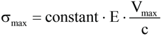
Vibration data is typically captured by acceleration sensors (i.e. accelerometers – Figure 1). In that case, it would be simplest to present the data in the format of acceleration versus time or acceleration versus frequency. In some cases other parameters might be more important such as clearance. For example, in rotary machinery it is not uncommon that the shaft displacement is monitored with proximity sensors near the bearing points. Displacement becomes smaller at high frequencies and acceleration becomes smaller at low frequencies. Vibration velocity is the derivate of acceleration and the integral value of displacement. Hence, it lies midway between displacement and acceleration and, thus, covers a broader central frequency range. Piping vibrations typically occur in a more central frequency range i.e. 10 to 1000 Hz, which makes vibration velocity an attractive parameter. Most importantly, it also relates to dynamic stress. For any linear structure vibrating at resonance the following correlation can be used:
 (Ref. 1)
The maximum dynamic stress equals to the ratio of maximum vibration velocity (Vmax) to the speed of sound in the material times the Elastic Modulus (E) times some constant (the proportionality factor). The constant is not expected to vary greatly, even over a wide range of system size, geometry, vibration mode and frequency. NUREG-1061 suggests a range of 1 to 3 for simple practical structural elements. The correlation works for any flexural vibration of beams (i.e. pipes) and plates with any practical section shapes and boundary conditions so that vibration velocity becomes an appropriate parameter to address the severity of structural vibration. What is an acceptable level? The allowable limits are somewhat dependent on system size, layout and mode of vibration. Hence, an acceptance criterion is best derived from a pipe stress report or seismic analysis. For cases where this information is not readily available, a rule of thumb would be convenient to have. The best way to develop a rule of thumb for vibration velocity as general severity criterion for pipe vibration is to correlate actual field experience data. The cases should cover a wide range of power plant and process plant piping systems.
Before we consider field experience, let’s first take a look at the governing design standard for vibration velocity limits for piping in nuclear plants i.e. ASME ANSI-OM3. This standard provides an allowable zero-to-peak velocity, which is derived from the linear stress-velocity relationship above. Engineers from EdF (Électricité de France) performed a study to verify if a general screening criterion of 12 mm/s would conservatively bound typical plant piping geometries by applying ASME ANSI-OM3 to 181 different piping setups. The setups covered most of the configurations that one would encounter inside a plant. All setups had adequate static and seismic designs that met regulatory design rules. 99.7% of the analyzed geometries displayed allowable velocities above 12 mm/s, which makes the proposed screening level appear very conservative.
On the other hand, NUREG-1061 considers field experience. It states that for typical power and process plant piping systems, including appended equipment and supports, the allowable level is approximately 40 mm/s. This is clearly a much higher allowable level than the theoretical value. One reason for the difference might be the use of linear boundary conditions in the analysis that have a tendency to cause higher stresses due to the rigidity of the model. Field experience likely provides a better value.
Since the age of a plant, operational wear, and general deterioration will have an effect on the fatigue strength as well, it is suggested to take that into consideration somewhat. Based on the experience at Fauske and Associates (FAI), it is recommended to use an allowable peak level of 25 mm/s for screening purposes.
Based on our field experience, vibration levels below this threshold should cause few, if any, problems. Vibration levels near this threshold are considered a rough running configuration. Small bore pipes have a tendency to undergo damage first. That is in particular true for unsupported configurations such as drains (drip legs) or sampling lines. These lines exhibit little damping and are easily excited. Tieback supports can provide quick remedy. Safety related equipment that is installed on the pipe line (e.g. automatic isolation valves) should be evaluated separately and is likely to require a lower allowable level.
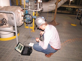
Figure 1 FAI Engineer Measuring Vibration Data on a Steam Valve Stem
In summary, vibration velocity is considered as an adequate general indicator of vibration severity and distress for piping systems. It can be used as acceptance criterion to assess the severity of piping vibration. The threshold at which the vibration levels are classified as unsafe must be derived from a stress analysis report. In the absence of a detailed analysis, it is recommended to use 25 mm/s peak vibration velocity as screening criterion. If you enjoyed this article, subscribe to our blog.
The text of this article was compiled with information and passages from the listed references.
References
1. NUREG-1061, Report of the U.S. Nuclear Regulatory Commission – Piping Review Committee, Evaluation of Other Loads and Load Combinations,
1984 FAI.
2. Sebastien C., A 12 mm/s Screening Vibration Velocity for Pipes Using ANSI-OM3 Standard and Regulatory Design Rules, ASME Pressure Vessels and
Piping Division Conference, 2005
3. ASME ANSI-OM3, Requirements for Preoperational and initial start-up vibration testing of nuclear power plant piping systems, 1982
For more information or to discuss, contact: Jens Conzen, Director, Plant Services, Fauske & Associates, conzen@fauske.com, (630) 887-5203, www.fauske.com